
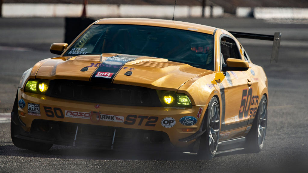
While Kelley and I were visiting family in Arizona, we had the opportunity to visit the garage of one of our long time customers and good friend, Chris Wynne of FTW Motorsports.

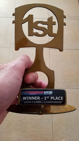
Chris is fresh from a 1st place win for 2018 in NASA Super Touring Championship, and gave us a replica of his trophy as a thanks for supporting his race program. Awesome!
CAN Bus goals
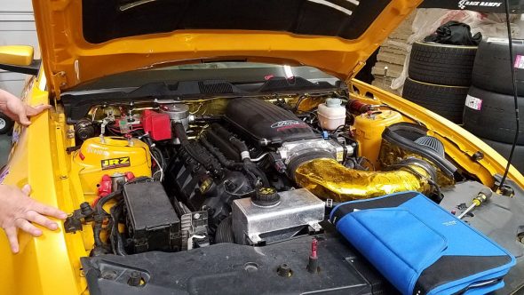
For a long time we’ve been talking about decoding additional CAN data from his 5th generation Ford Mustang. At the time, Chris was getting basic data from OBDII, blended in with direct readings from additional sensors he added for race-specific needs. We both knew there was a wealth of information just waiting to be exposed via Ford’s high speed CAN Bus, so this trip was an opportunity to take a crack at it.
The goal was to get some information that was not available over standard OBDII, such as steering angle, brake pressure, and wheel speeds.
Prior to our visit, a discussion in the Autosport Labs Community Facebook group prompted us to create a simple Lua script that auto-generated and updated channels for any CAN data received by RaceCapture, tracking up to 100 virtual channels that can be created in Lua scripting. So, on the drive to Arizona, I whipped up a sample script in advance and stashed it for when we were ready to test.
The timing for this test was good as Chris was ready to pull the tired race motor – so the last act of service the motor will give will be to help unlock some CAN secrets!
Spoiler: we won
The great part is we decoded everything we set out to accomplish, and we have a new CAN Bus preset for 2011-2014 mustangs – but read on for the full story!

Decoding some initial data
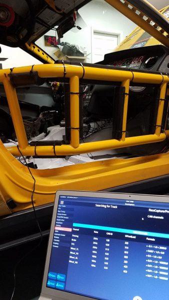
First impression: Wow, the 5th gen Ford Mustang pumps out a ton of data! The custom Lua script worked, albiet with it’s share of hiccups. We immediately hit the 100 channel limit as it was creating one channel for every byte of the CAN message it would detect- up to 8 channels per CAN ID. It seems that the Ford engineers were quite enthusiastic about dumping as much data as possible onto the Mustang’s high speed CAN Bus! With the number of channels spilling over I was concerned the data we would want might be hidden in the CAN IDs we could not see, but we forged ahead regardless.
Steering Angle Sensor
For our first channel we picked something that would seem easy to detect: Steering angle. With the Mustang switched to ‘on’ and engine ‘off’, Kelley moved the steering wheel left and right while I scanned up and down RaceCapture’s raw channel view watching for updates in the CAN data that would coincide with the movement of the steering wheel. And to our surprise, we spotted it almost immediately! Fortunately, one of the CAN IDs it picked up initially contained the steering angle data.
We saw the steering data on CAN ID 128 (decimal), with values updating on offset 2 and 3. I switched to the CAN mapping screen under Setup and quickly created a channel that mapped a 16 bit, signed, big-endian value into a channel named “Steering”. We noticed the value was updating smoothly as we moved the wheel left to right – a good indicator!
Next, with the wheel centered, we noticed the raw value was showing 20000. Thinking this might be an offset, we edited the formula to offset the value by -20000 – and then bam! we got a zero reading at steering wheel center, with the value going negative and positive corresponding to wheel movement.
Then, we noticed when Kelley moved the steering wheel exactly 90 degrees to the left or right, the raw value indicated approximately 850-1000. Some finer inspection led us to notice that the raw value was actually in degrees – but scaled in 0.1 degrees. So we updated the formula to multiply the value by 0.1 and changed the offset to 2000 (from 20000).
Now we were getting actual degrees of rotation! Next, we asked – which direction should indicate positive or negative steering angle? We made an executive decision and determined that right turns were positive, and left was negative. So, the final formula settled on a multiplier of -0.1, with an offset of +2000.

And steering angle was fully decoded!
Brake Pressure Sensor
Our project’s overall goal was to create a complete driver behavior profile: that is, getting data for steering, brake, and throttle. On the heels of the successful steering angle mapping, we picked brake pressure as the next channel to tackle.
Running the CAN analysis script again I scanned up and down RaceCapture’s raw channel view while Chris pressurized the brakes on a roughly 2 second interval, calling out when he pressed and released the brakes. And just like that, we spotted the CAN data value that was smoothly updating according to brake pressure. The value was updating on CAN ID 529, offset 7.
In this case, we only identified a single byte updating, so we mapped just a single byte channel in the CAN mapping. Next, we rationalized what the units should be for this channel: while we could do the research to figure out the actual units output by this sensor – PSI or Bar – we felt a somewhat more abstract value would be more useful for the purposes of data analysis. So, we settled on a % indicator, where 0% was no brakes, and 100% represented “really freaking hard braking”.
So, we created the CAN mapping channel and tracked the raw value with no scaling, which served as a good starting point.

With the engine off, we could only generate raw values in the 70-90 range. Chris suggested we start the engine to generate some vacuum for the brake booster. Sure enough – “super ultra max brake pressure” yielded a max raw value of ~150. We scaled the raw value by 0.667 to make this absolute max brake pressure register as 100%. We figured this was good enough – and make a nice counterpart to throttle position %.
Throttle Position Sensor
Another seemingly easy task was to figure out throttle position. From research, Chris warned that throttle-related data should appear in multiple places in the CAN stream, and sure enough – I saw multiple values updating that seemed to correspond to changes in throttle. Some were updating smoothly, and others seemed to change value with throttle, but not exactly linear with pedal position. Knowing our goal was to find the data that corresponded with actual commanded pedal position, we found a CAN ID that seemed to do that: CAN ID 513, offset 6, with data just showing in 1 byte.
Since the Mustang has a drive-by-wire system, we knew that the ECU could still be fooling us – but after observing the direct behavior of the throttle body as it correlated to throttle position – and also directly manipulating the throttle plate, we were pretty confident we had what was commanded throttle position.

At WOT the raw value indicated was ~199-200, so we scaled the value by 0.5 to get a 0-100% range and called it a day.
Wheel Speed Sensors
The bonus channels we wanted to get were the individual wheel speeds. With the Mustang on jack stands it was easy to spin the wheels – but would we spot the data?
Yep, it was easy. Front-left wheel speed was immediately spotted on CAN ID 533, offset 0. 2 bytes were updating as the wheel speed was adjusted, so we quickly created a mapping.
We noticed the static ‘zero’ value was actually 10000 – an inexplicable offset that only the Ford engineers would know why. Chris found a forum post (ironically a post on the Autosport Labs forums) discussing the wheel speed data for the Ford Focus. There it was also offset by 10000, and the suggestion was to offset it by that amount in the mapping. The raw value scaling was also in 1/100 KPH, so we set the formula multiplier by 0.01 and adjusted the offset to -100.0 (since the multiplier is applied before the adder, due to operator precedent).

We quickly found the remaining wheel speed channels on CAN ID 533, offset 2 for Right Front; offset 4 for Left Rear; and offset 6 for Right Rear.
Summary and Take-Aways
CAN Bus reverse-engineering: it’s easier and faster than you may fear

With the right tools and a friend to help, sifting through the CAN data stream is actually easier than Neo decoding the Matrix. I was actually surprised how fast we were able to detect and decode the channels.
Using RaceCapture to reverse-engineer CAN Bus data is very effective
Once again, the power of RaceCapture’s Lua scripting engine really shines, showing the system can perform feats and tricks it was never originally designed to do.
The script is definitely clunky compared to dedicated CAN Bus analysis software, but it certainly did work as a tool to identify changing patterns in CAN Bus data – proving you could get this done armed with just the RaceCapture app running on a tablet – even during some idle time in the race paddock.
A hat-tip to the Ford engineers
We have to hand it to the Ford engineers – aside from some curious value offsets that only an insider would know, they mapped their data in very clean 8 or 16 bit chunks with sane value mappings. No weird binary masking or sub-bit decoding required – it all decoded very quickly.
Getting started with your own reverse-engineering project
It’s easy to replicate what we accomplished here – just copy and paste the CAN Bus reverse-engineering script into your Lua scripting window under the RaceCapture app Setup and start peering into the data your car is streaming.
Want to learn more about RaceCapture’s Lua scripting?
We have a full guide here, including numerous script examples, on how to customize the behavior of your RaceCapture system.
What are you going to reverse-engineer?
Share your thoughts in the comments, we’d love to hear your goals and results!
Awsome work autosport, following
Brent, This is awesome, I am working with a 2012 Mustang GT, I am swapping it into a 70 Mustang Fastback, and I have been thinking of the things I would like to do, one is an automatic spoiler goes up at a certain speed and down at a certain speed, Im not sure how to make this happen, but I guess that your Can-Bus work here has made it closer than ever. Thank you for posting, this as a very interesting read.
I believe the offset of 10000 for speed is to indicate there is actual data present. If no offset then you wouldn’t know if the wheel speed is 0 or there was a faulty reading. Important to know when this data is an input to for safety critical things such as things like cruise control!